|
If you want to use any images or text from this site you must get written approval first. Click HERE to send an email request explaining your intended usage. |
| The Commodore 128 existed in three different major board versions: The first board was used in the flat 128 and in the plastic-cased 128D. Then came the 128DCR board, with the floppy controller integrated on the motherboard. There was also a 128CR (cost-reduced flat 128). | |
| ../ | [Parent directory] |
| drives@ | Disk drives |
| firmware@ | System firmware |
| manual/ | Service manual |
| power/ | Power supply schematics |
| Date | Size | Filename | Description | |
|---|---|---|---|---|
| 1996-11-27 | 118674 | 310378-1-left.gif | ||
| 1996-11-27 | 113712 | 310378-1-right.gif | ||
| 1996-11-27 | 99301 | 310378-2-left.gif | ||
| 1996-11-27 | 107805 | 310378-2-right.gif | ||
| 1996-11-27 | 130766 | 310378-3-left.gif | ||
| 1996-11-27 | 77337 | 310378-3-right.gif | ||
| 1996-11-27 | 99507 | 310378-4-left.gif | ||
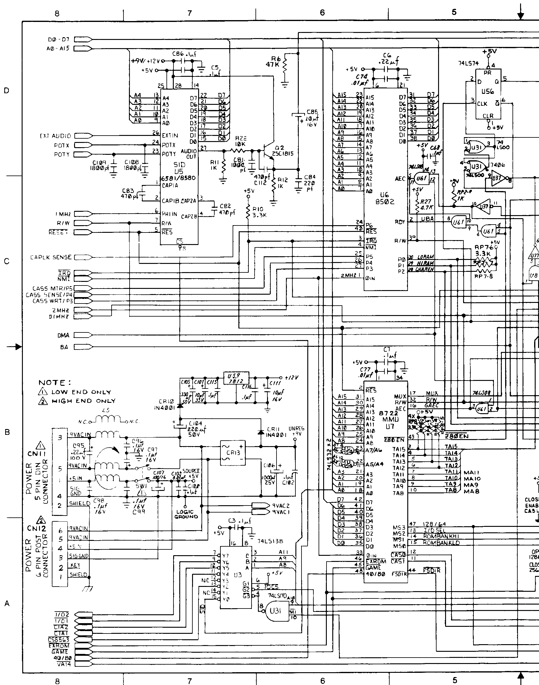
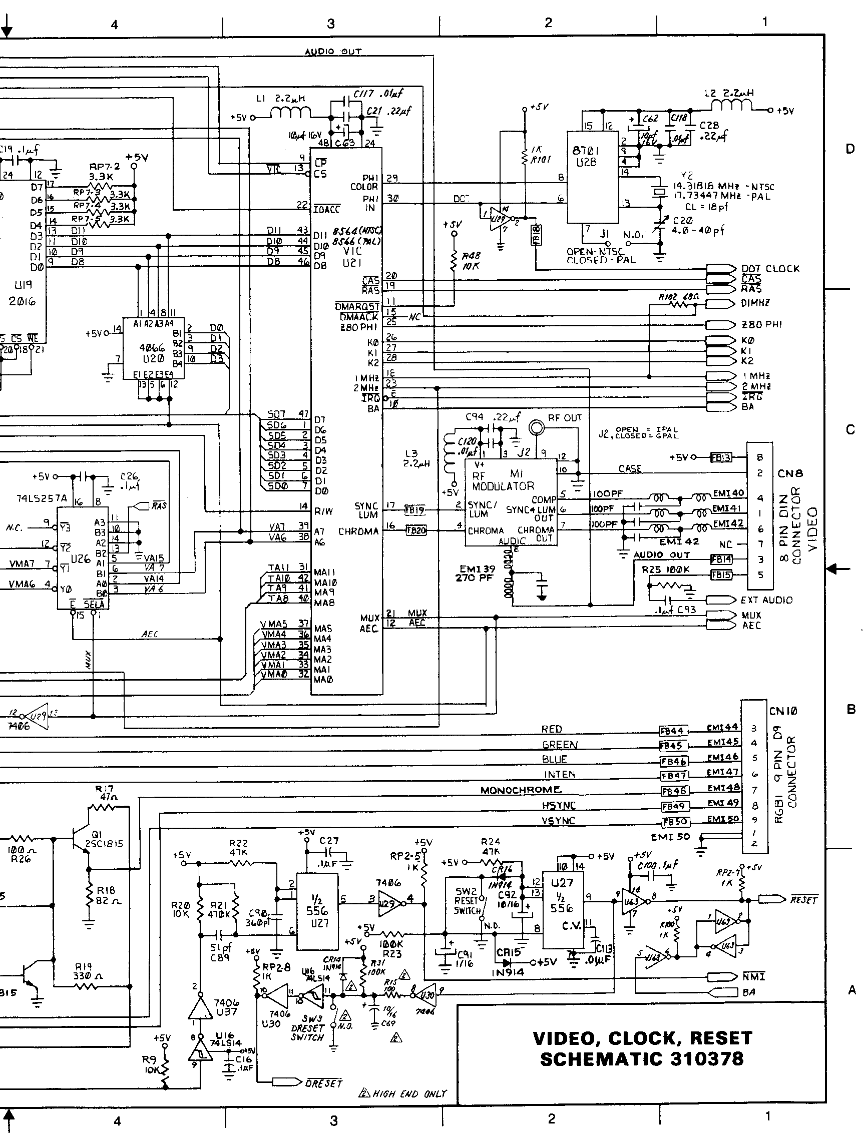
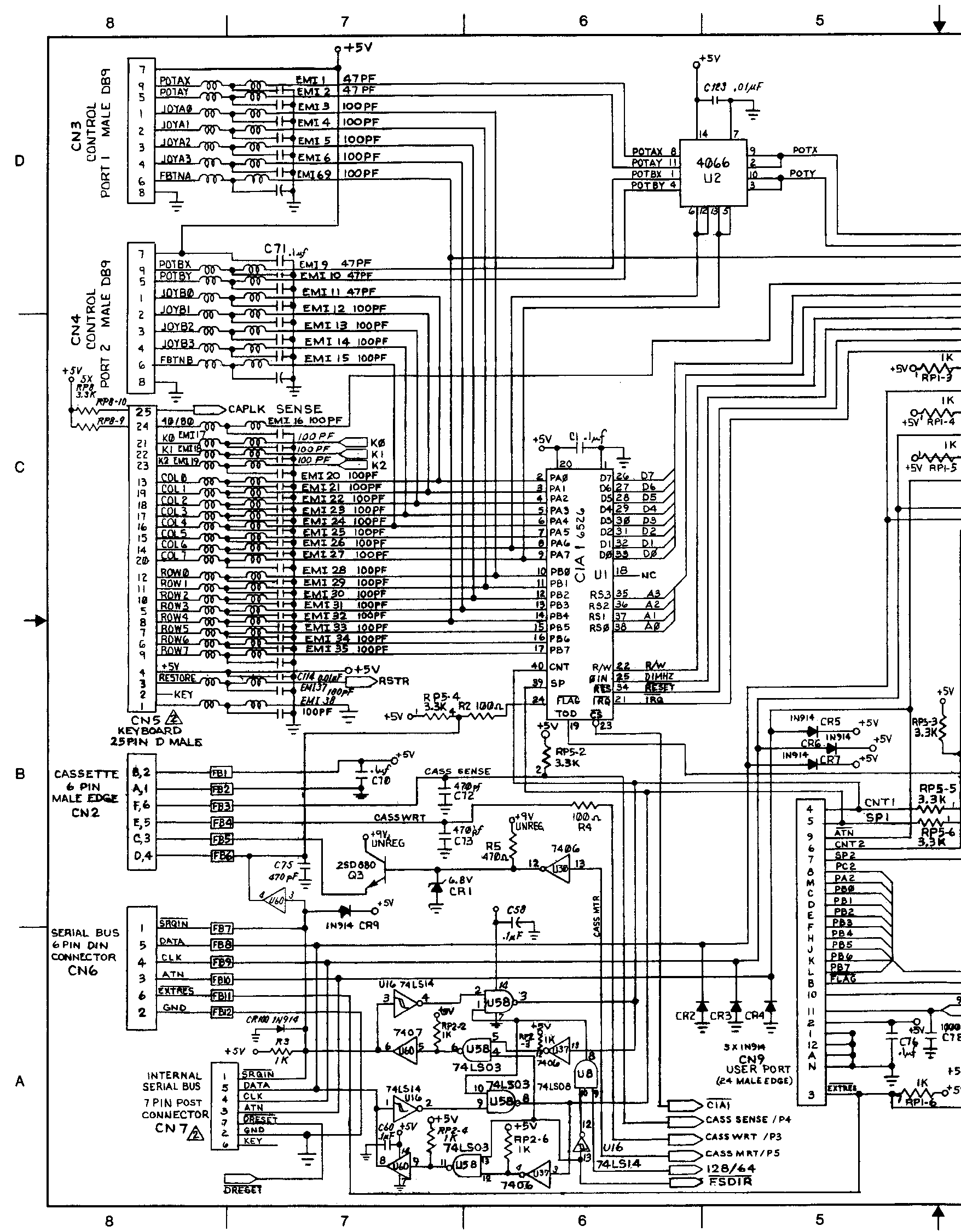
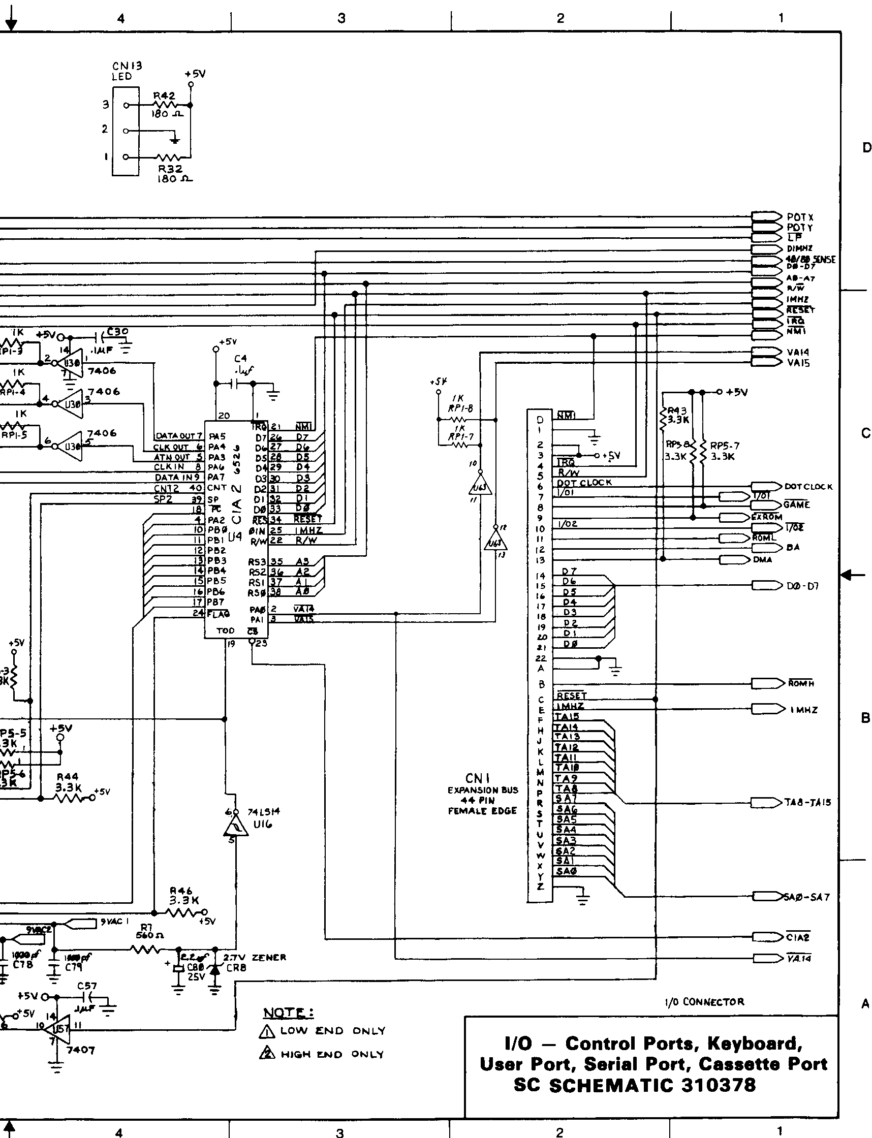
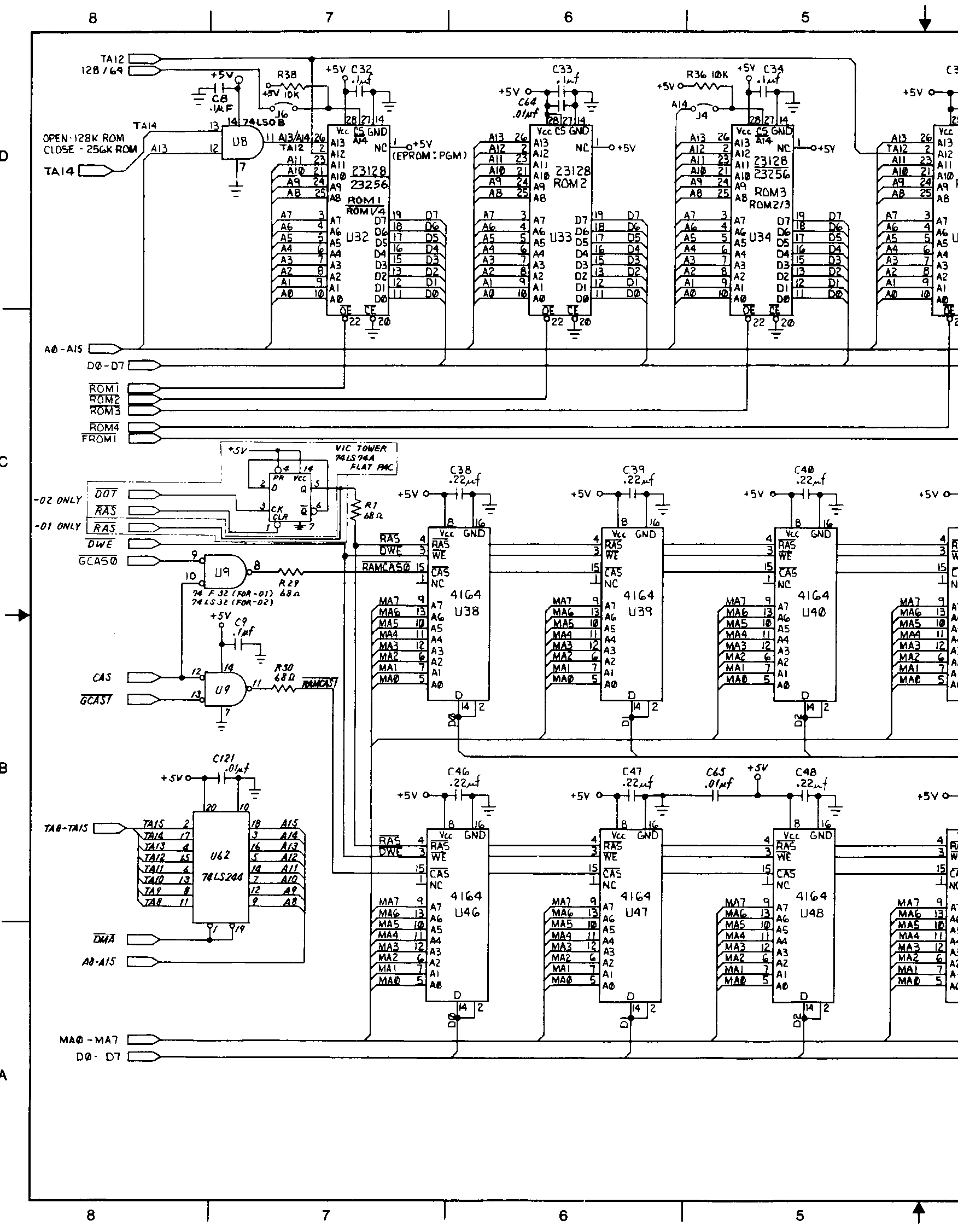
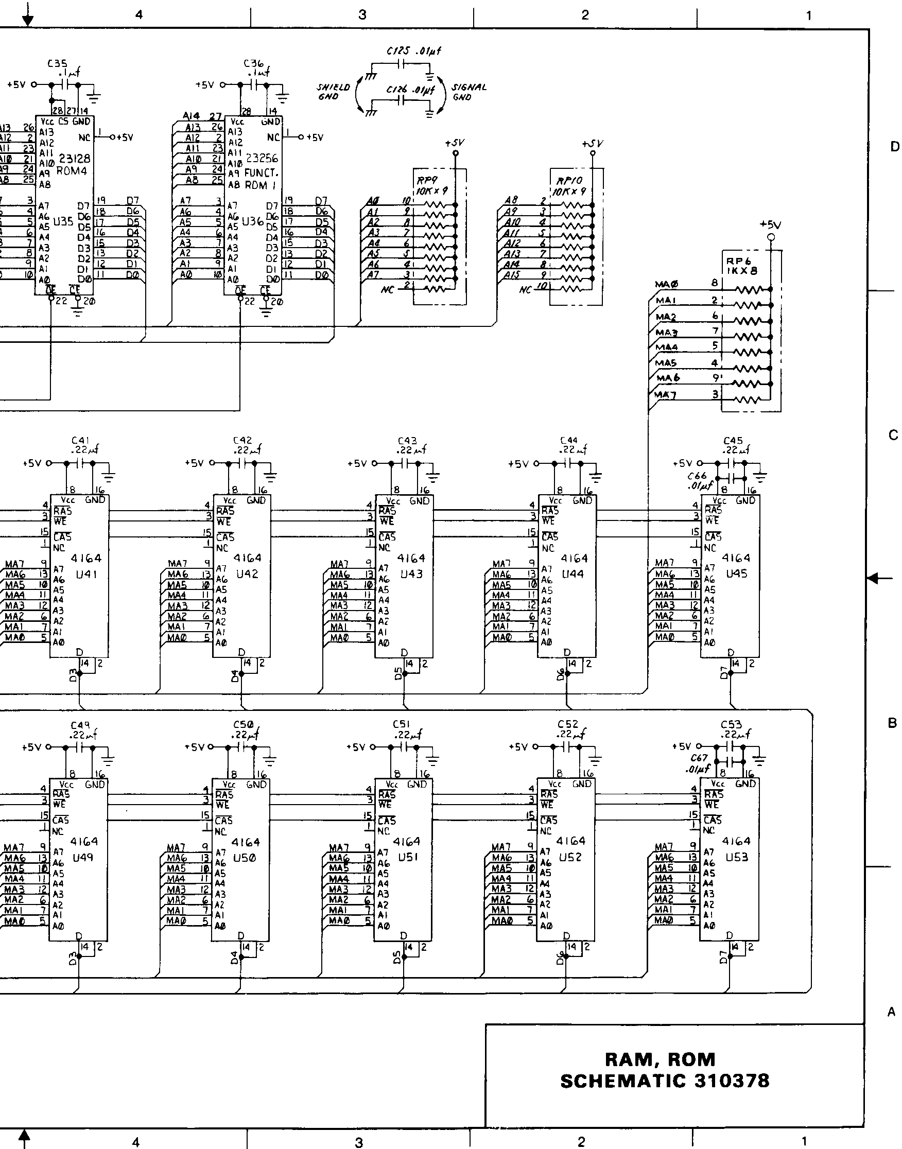
| 1996-11-27 | 90149 | 310378-4-right.gif | These are the schematic diagrams of the Commodore 128 main board ("flat C128" and C128D in plastic case). They were on eight pages in the Commodore 128 Programmer's Reference Guide, two pages containing one engineering sheet. | |
| 1998-05-15 | 747229 | 310378-update.zip | Update to the Commodore 128 Service Manual, containing the two revised pages in the 310378 schematic revision 7A. | |
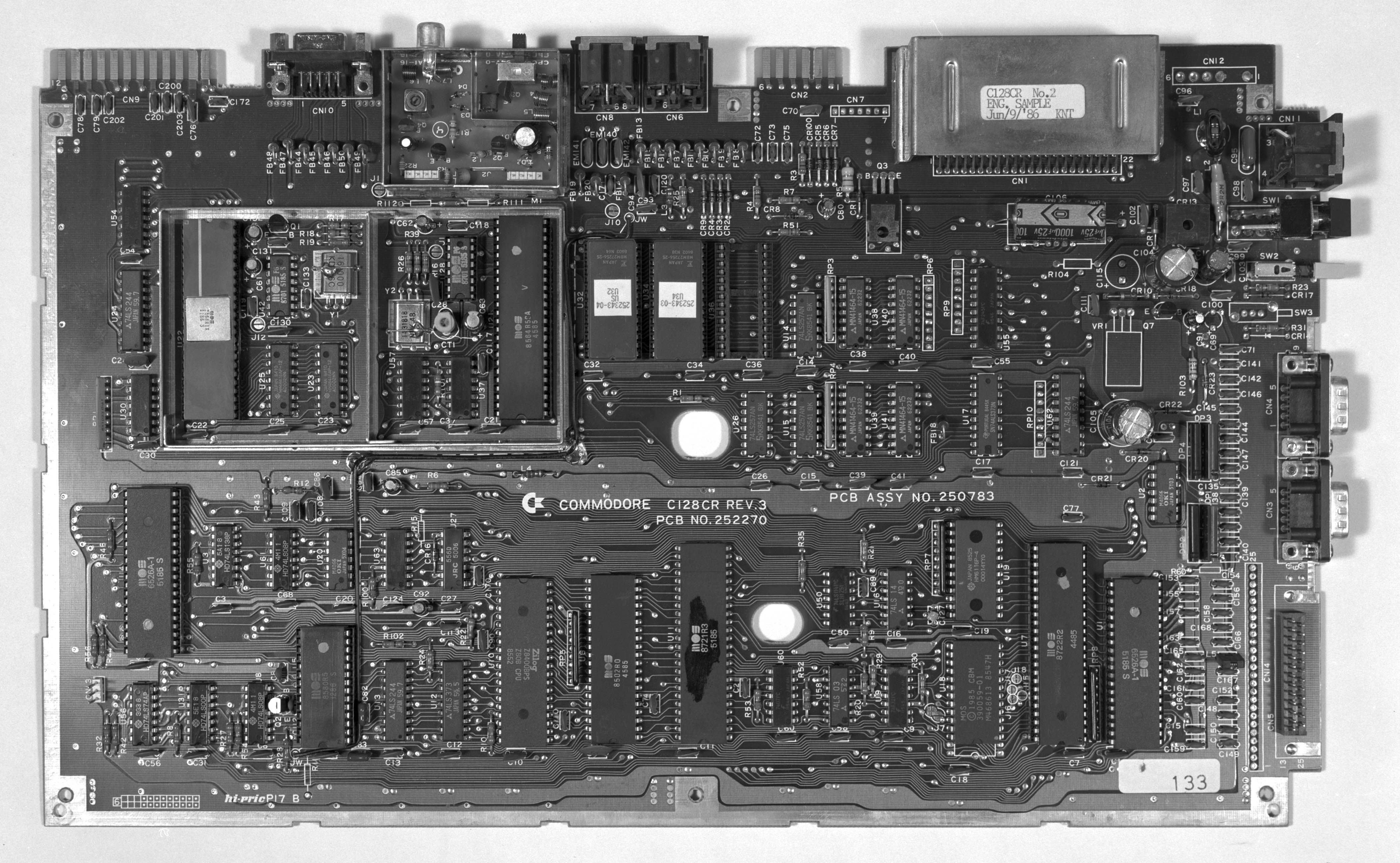
| 2000-02-23 | 1115174 | c128cr.jpg | A black&white picture of a cost-reduced flat Commodore 128 circuit board. This model never entered mass production; this is an engineering sample possessed by Raymond Carlsen. The board says "PCB ASSY NO. 250783", "C= commodore C128CR REV.3", "PCB NO. 252270", and "C128CR No.2 ENG. SAMPLE Jun/9/'86 KNT". | |
| 1996-12-13 | 172416 | c128dcr-1-left.gif | ||
| 1996-12-13 | 90870 | c128dcr-1-right.gif | ||
| 1996-12-13 | 143437 | c128dcr-2-left.gif | ||
| 1996-12-13 | 148206 | c128dcr-2-right.gif | ||
| 1996-12-13 | 128384 | c128dcr-3-left.gif | ||
| 1996-12-13 | 134398 | c128dcr-3-right.gif | ||
| 1996-12-13 | 77902 | c128dcr-4-left.gif | ||
| 1996-12-13 | 58823 | c128dcr-4-right.gif | ||
| 1996-12-13 | 126315 | c128dcr-5-left.gif | ||
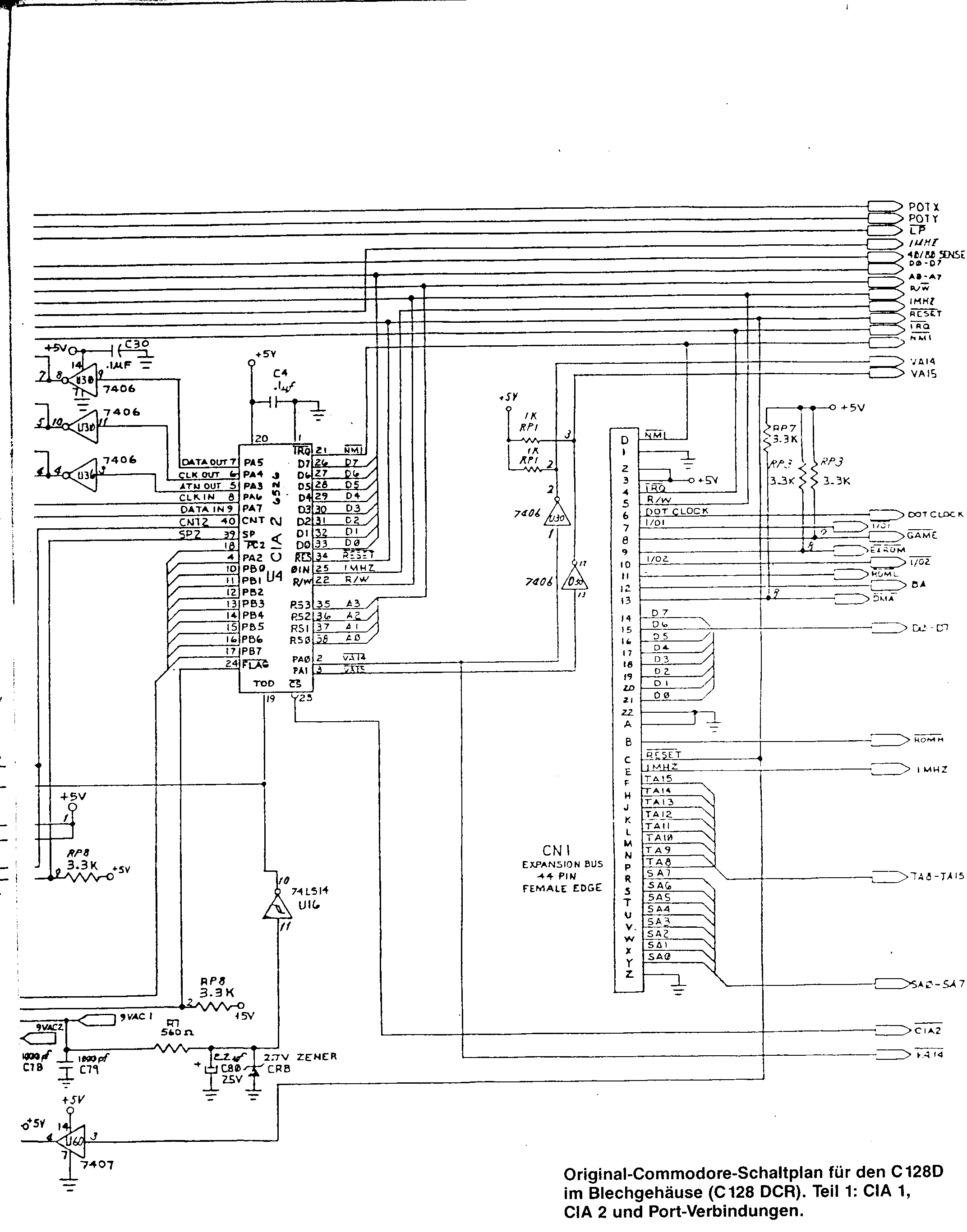
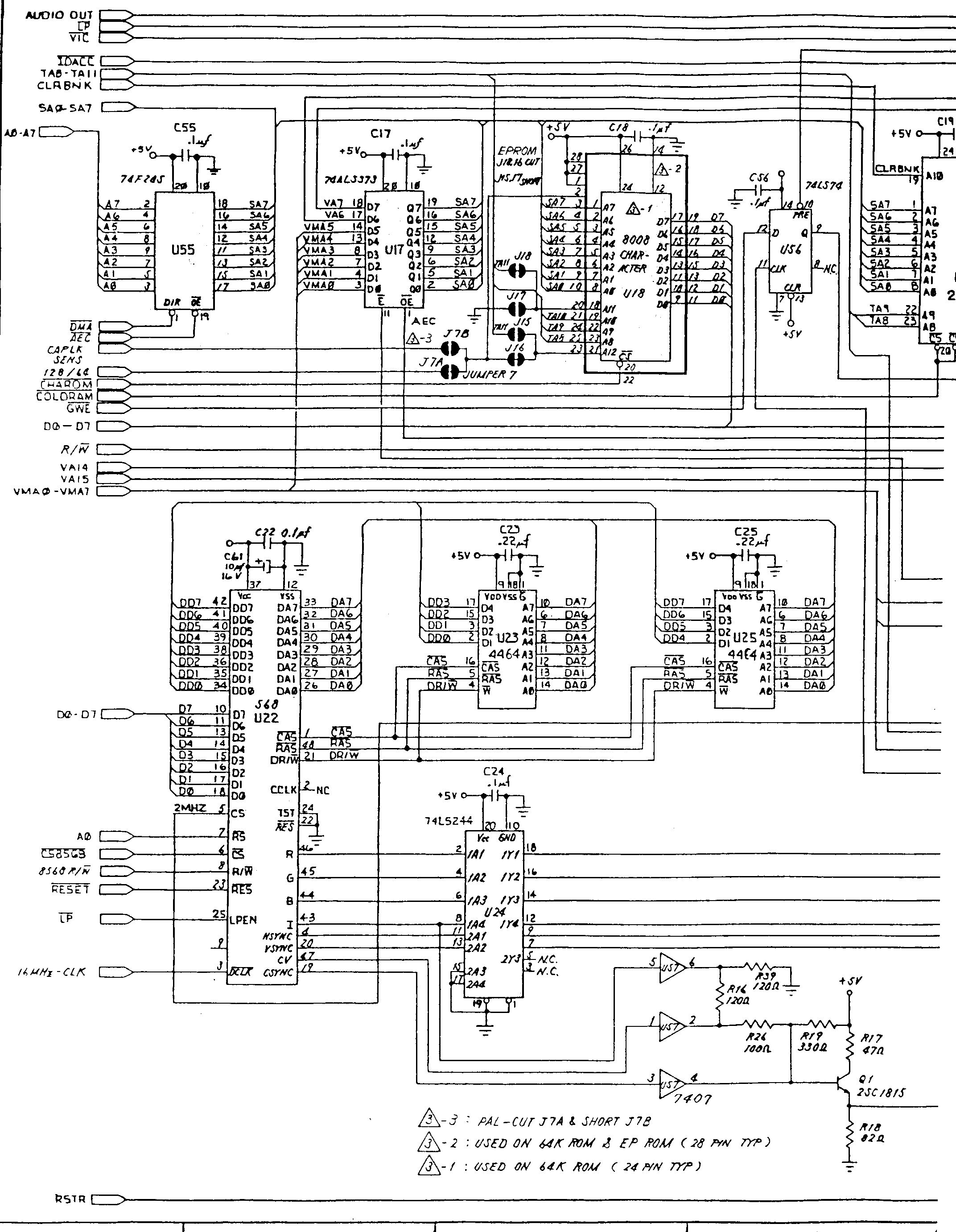
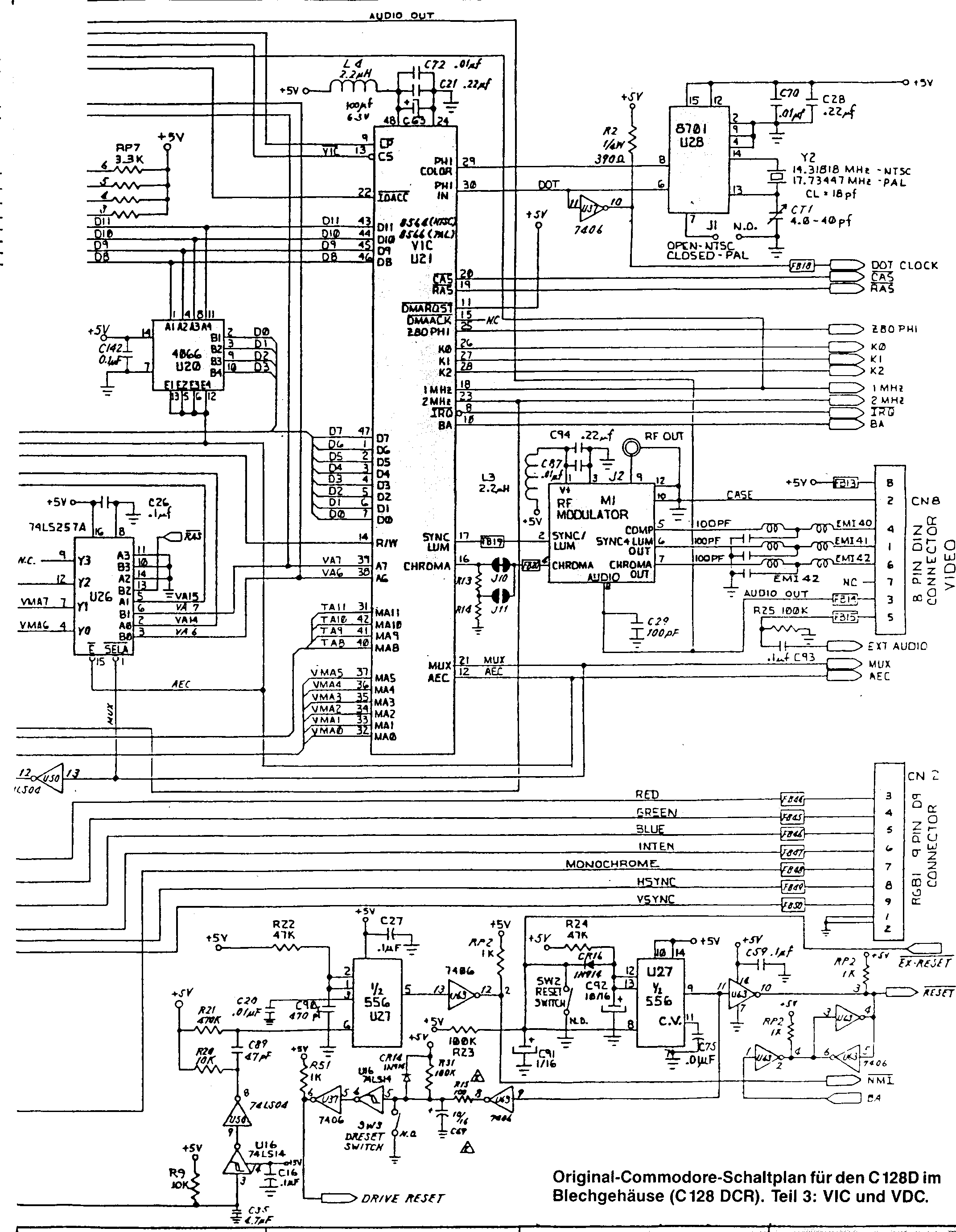
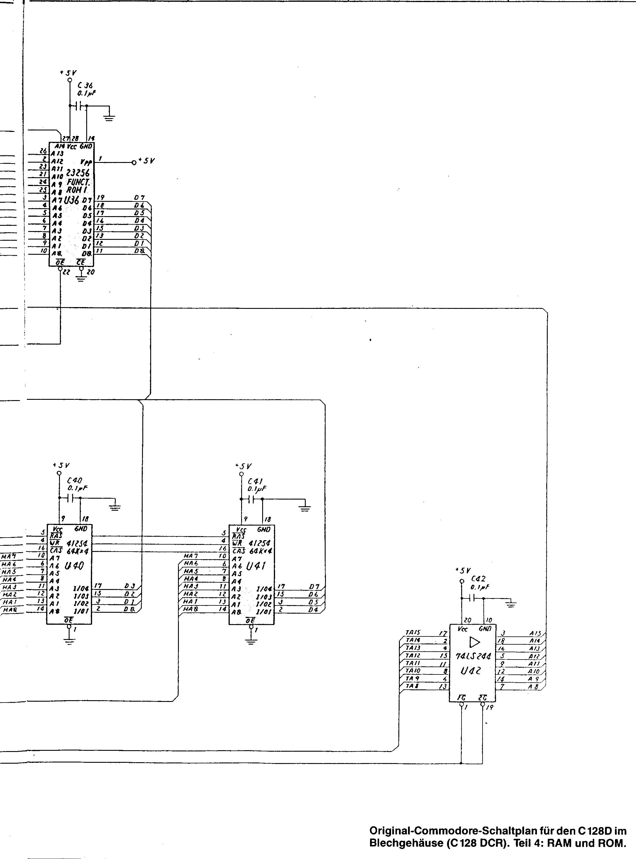
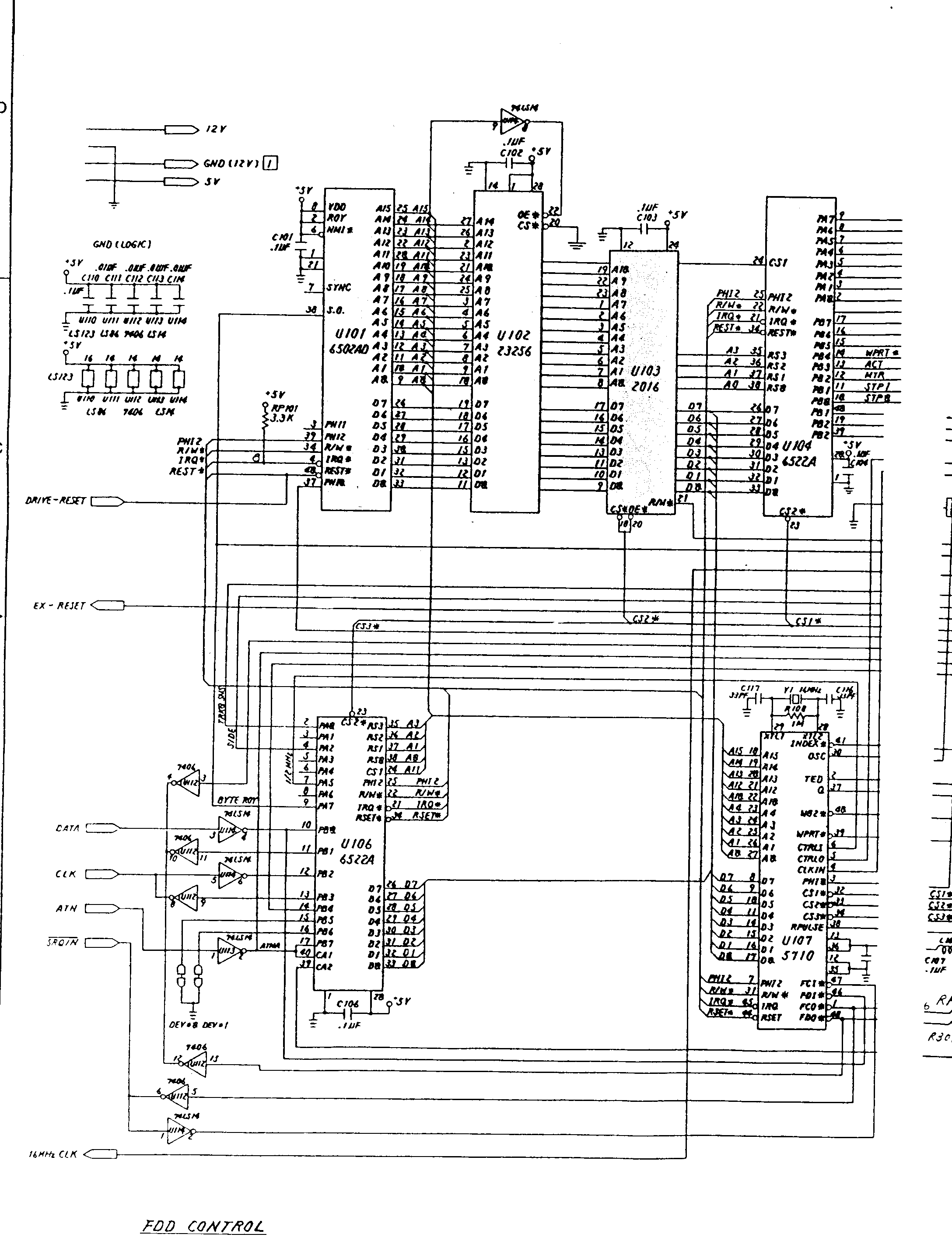
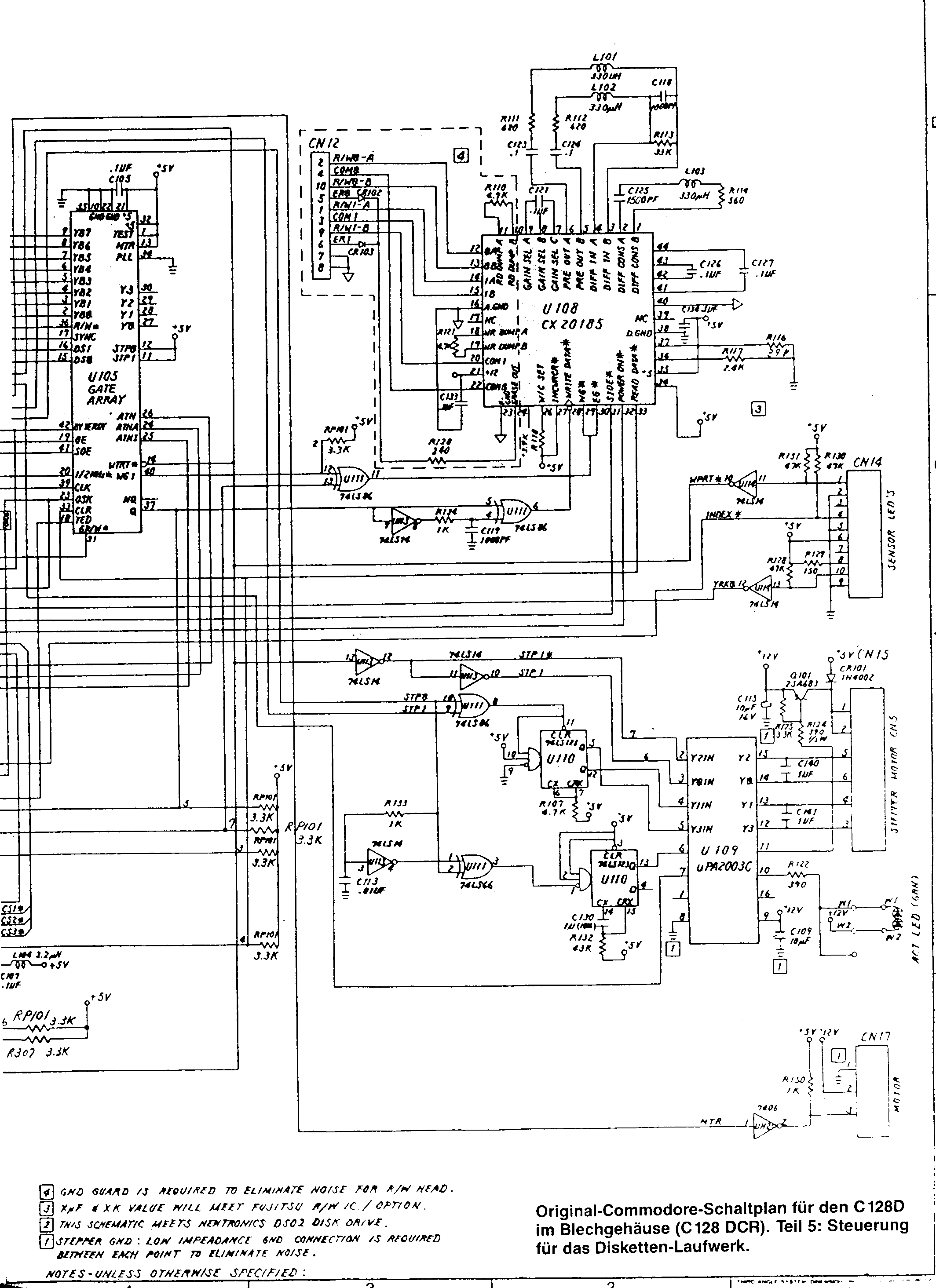
| 1996-12-13 | 144315 | c128dcr-5-right.gif | These are the schematic diagrams of the Commodore 128DCR main board
(metal case C128D with built-in 1571CR floppy controller). The diagrams
were scanned from a 64'er Sonderheft, and they appear to be a copy of
schematic 252451. According to Nicolas Welte, there is an error on the right half of page 5. The 74LS14 hex Schmitt-trigger inverter U113, pin 13 is connected to WPRT* (misprinted WTRT* on U105), which doesn't make any sense. Obviously it should be connected to STP1 instead, which is three lines more to the right! |
[FTP://NIC.FUNET.FI/pub/cbm/schematics/computers/c128/ | SunSITE ftp | SunSITE http]
[email protected]
|
If you want to use any images or text from this site you must get written approval first. Click HERE to send an email request explaining your intended usage. |